C3Fire Simulation Documentation
Simulation
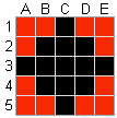
The simulation in C3Fire is build up by a set of interacting simulation layers. The main layers are a geographical objects layer, a fire layer and a unit layer. All layers are based on a two dimensional matrix. Nothing exists outside the matrix and the fire will not spread outside this area. In the geographical objects layer there can be different kinds of vegetation, houses and other types of static objects. The fire layer is a cellular automata interacting with the other layers. In the unit simulation layer different kind of moveable objects exist, example emergency units as fire-fighting units, and reconnaissance persons. There also exist a weather simulation that interacts with the fire simulation.
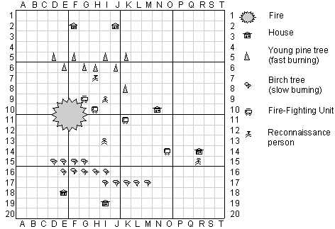
Figure 1. Example on a map matrix.
Map layer
The matrix of C3Fire is the surface on which the other layers can interact. Nothing exists outside the matrix. The fire will not spread outside this area. Weather, units and geographical objects cannot be configured to have any meaning outside it.
In the standard experiment setting of C3Fire the matrix is exposed upon a background image that are defined in session configuration file at
Map Config. In the configuration also other properties, as dimension size, index type and color of lines, of the matrix are set.
Fire Simulation
The fire simulation is a cellular automata. Each position on the map has its own fire simulation, together they represents the fire. The fire's start positions are determined in the session configuration, but how the simulation develops is depending on each positions fire simulation. The geographical object layer, the unit layer and the wind simulation affect the fire simulation.
Fire States
In the standard experiment setting, the fire in each position in the geographical matrix could be in one of five states: clear, fire, closed-out, burned-out, fire-break.
|
Clear |
The position is not burning. It will be ignited when a burning neighbour position has burned a certain length of time, the ignition time. |
|
Fire |
When a fire is burning, it will keep burning until it is closed out by a fire-fighting unit or is burned out due to lack of fuel. This burning position ignites fire on its neighbour positions. |
|
Closed Out |
A fire-fighting unit has extinguished the fire on the position. It cannot be ignited again. |
|
Burned Out |
The fire on this position has burned out due to lack of fuel. It cannot be ignited again. |
|
Fire Break |
All types of burnable fuel has been removed, burned or secured. It cannot be ignited. |
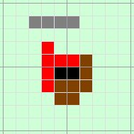
The states of fire are represented on the map by four images, no fire, fire, fire closed out, fire burned out or fire break.
Example of standard images:
|
No fire |
| |
|
Fire | ||
|
Fire closed out | ||
|
Fire burned out | ||
|
Fire Break |
Fire Spread
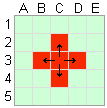
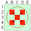
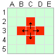
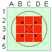
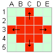
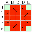
A non-burning position can be ignited if a burning neighbour position has burned a certain length of time. The fire can spread from one position to the nigbours, horizontally (West and East), vertically (North and South) and diagonal (North-West, North-East, South-East and South-West). To make the fire spread in a circle, the fire spread are slower in the diagonal. The fire spread delay are (1.4142) times as long for the diagonal directions than for the horizontal and vertical directions.
|
Fire spread |
Fire spread |
When a fire has ignited, a fire-fighting unit can extinguish the fire or the fire can burn itself out due to lack of fuel. A new fire cannot be ignited at a position, which has been closed out, burned out or is protected by a fire break.
The fire simulation layer is interacting with the geographical object layer, the unit layer and the wind simulation. This means that the spreading speed and the spreading direction of the forest fire are dependent on the vegetation, the activities of the fire-fighting units and the wind. The decision makers need to understand the characteristic behavior of the fire in different types of vegetation and weather conditions to be able to perform their task in a suitable way.
Fire Simulation
The Fire simulation is defined in the Fire configuration definitions in the session configuration. In the configuration the manager can select wind factor, ignite time and burn out time, all of them affects the fire simulation.
<FireConfig
  WindFactor = "0.8"
  IgniteTime = "10"
  BurnOutTime = "20" >
Ignite time
The ignite time defines how long time it takes for a normal cell to ignite a neighbour cell. The value defines number of seconds. To make the fire spread in a circle, the fire spread are slower in the diagonal. To north, east, west, south and west the time delay are the ignite time. While to north-west, north-east, south-east and south-west the time delay are the (ignite time * 1.4142).
Example
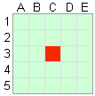
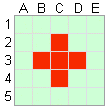
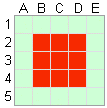
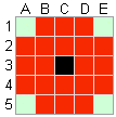
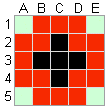
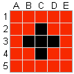
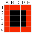
If objects in the cells have the fire speed equals "1" Object Type Configuration and the wind speed equals "0" Scenario Configuration. Then it is only the ignite time in the fire configuration that influence the fire spreading speed.
|
Step 1 |
Step 2 |
Step 3 |
Step 4 |
Step 5 |
In this example the Ignite time = "10" (10 seconds)
|
Step 1 |
Time 00:00:00 |
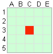
The fire starts at C3. |
|
Step 2 |
Time 00:00:10 |
10 seconds after C3 starts burning the fire spreads from cell C3 to cell B3, C2, C4 and D3. |
|
Step 3 |
Time 00:00:14 |
14 seconds after C3 starts burning the fire spreads from cell C3 to cell B2, D2, B4 and D4. |
|
Step 4 |
Time 00:00:20 |
10 seconds after C2 starts burning the fire spreads from cell C2 to cell C1, etc. |
|
Step 5 |
Time 00:00:24 |
14 seconds after C2 starts burning the fire spreads from cell C2 to cell B1 and D1, etc. |
BurnOut Time
The burnout time defines how long time it takes for a normal cell burn down.
The value defines number of seconds. The burn out time are unaffected by the objects fire speed and wind speed.
Example
Same fire ignite time as the example above.
|
Step 1 |
Step 2 |
Step 3 |
Step 4 |
Step 5 |
|
Step 6 |
Step 7 |
Step 8 |
Step 9 |
Step 10 |
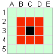
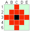
In this example the BurnOut time = "15" (15 seconds) and the Ignite time = "10" (10 seconds)
|
Step 1 |
00:00:00 |
The fire starts at C3. |
|
Step 2 |
00:00:10 |
10 seconds after C3 starts burning the fire spreads from cell C3 to cell B3, C2, C4 and D3. |
|
Step 3 |
00:00:14 |
14 seconds after C3 starts burning the fire spreads from cell C3 to cell B2, D2, B4 and D4. |
|
Step 4 |
00:00:15 |
15 seconds after C3 starts burning the cells buns out. |
|
Step 5 |
00:00:20 |
10 seconds after C2 starts burning the fire spreads from cell C2 to cell C1, etc. |
|
Step 6 |
00:00:24 |
14 seconds after C2 starts burning the fire spreads from cell C2 to cell B1 and D1, etc. |
|
Step 7 |
00:00:25 |
15 seconds after C2, B3, D3 and C4 starts burning the cells buns out. |
|
Step 8 |
00:00:28 |
14 seconds after B2 starts burning the fire spreads from cell B2 to cell A1, etc. |
|
Step 9 |
00:00:29 |
15 seconds after B2, D2, B4 and D4 starts burning the cells buns out. |
|
Step 10 |
00:00:35 |
15 seconds after C1, A3, E3 and C5 starts burning the cells buns out. |
Wind
The fire simulation is influenced by the wind. When the wind is strong the fire spreads faster in the same direction as the wind blows. The wind speed and direction is defined in the scenario configuration Scenario Configuration. How much the wind should influence the fire development is defined with the wind factor value in the Fire configuration.
The main part of the fire spread calculations are :
Fire ignite time for neighborhood = igniteTime *(1-(windFactor*windSpeed*0,1)*Math.cos(windDirection))
Example
- The objects in the cells have the fire speed equals "1"
- The wind direction are from south towards north.
- Ignite time = 10
- WindFactor = 0.8
Then the time delay before the fire spreads to a neighbor cell will be as below.
|
|
|
|
Time delay in seconds before the fire spreads from the center cell to the neighbor cells.
Geographical Objects
The geographical environment in C3Fire is built up of vegetation and building objects. The vegetation is of different kinds of tree types, each with its own burning qualities (fast / slow burning). The objects, such as a house, also have their burning qualities.
The geographical environment will create complex decision task for the trained people. It will create a complex goal situation, where the staff can decide to protect some houses or some large forest area. During a session the fire-extinguishing organization should use the information about the environment in their strategic thinking to understand which areas need to be saved and where critical fast-burning forest areas are.
Objects
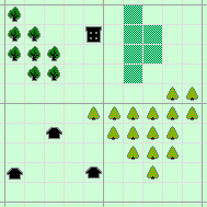
In the standard experiment setting there are three types of vegetation: normal, young pine tree (fast burning), and birch tree (slow burning). It is also possible to add swamp or water that is not burning at all. In the standard experiment setting it also can exist houses and schools. The role of the houses and schools are to make some areas more important to save than others.
Example of standard images:
|
Normal |
| |
|
Birch | ||
|
Pine | ||
|
Swamp | ||
|
House | ||
|
School |
The Object types are defined in session configuration file at Object Types. The objects that should exist in the simulation are defined at Objects. The objects that shall be visible in the users map are defined at Display Objects.
The different configurations for what objects that should exist in the simulation (the simulated reality) and for what objects that should be visible on the users map at the beginning of the session, makes it possible to define a map that differ from the simulated reality.
Fire in Vegetation and Objects
The fire simulation is influenced by the vegitation and objects in the geographical environment. All vegetations and objects has a fire speed value that are defined in the session configuration, See Object Type configuration. In the fire simulation the ignite time for a cell is calculated by multiply the normal ignite time with the fire speed factor of the object.
NewIgniteTime = IgniteTime * FireSpeed
Example
|
Normal |
FireSpeed = 1 |
Normal | |
|
Pine |
FireSpeed = 0.5 |
Fast | |
|
Birch |
FireSpeed = 2 |
Slow | |
|
Swamp |
FireSpeed = 0 |
Can not burn |
|
Step 1 |
Step 2 |
Step 3 |
Step 4 |
|
Step 5 |
Step 6 |
Step 7 |
Step x |
In this example the Ignite time = "10" (10 seconds) and the wind speed equals "0"
|
Step 1 |
00:00:00 |
The fire starts at C3. |
|
Step 2 |
00:00:05 |
5 seconds after C3 starts burning the fire spreads from cell C3 to cell D3. |
|
Step 3 |
00:00:10 |
10 seconds after C3 starts burning the fire spreads from cell C3 to cell C2. |
|
Step 4 |
00:00:14 |
14 seconds after C3 starts burning the fire spreads from cell C3 to cell B2 and D2 |
|
Step 5 |
00:00:15 |
10 seconds after D3 starts burning the fire spreads from cell D3 to cell E3. |
|
Step 6 |
00:00:19 |
14 seconds after D3 starts burning the fire spreads from cell D3 to cell E2 and E4 |
|
Step 7 |
00:00:20 |
20 seconds after C3 starts burning the fire spreads from cell C3 to cell B3. |
|
Step x |
xx:xx:xx |
B4, C4 and D4 does never starts to burn. |
Unit Simulation
In the C3Fire simulation the objects that moves around in the geographical area and interacts with the environment are called units. In the basic experiment setting there exist only fire-fighting units controlled by players.
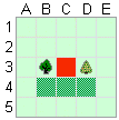
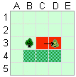
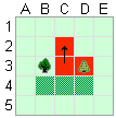
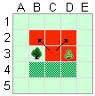
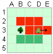
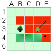
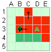
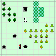
The unit is represented on the map by two images, the unit's current actual position on the map and the unit's intended position. The intended position is the position that an unit is moving towards. The intended position is displayed when a player want the unit to move to a new location. If the user selects the position or the intention, a read square is displayed around the image.
Usually all units are represented by numbers.
Example of standard images for Fire Fighting Unit number one.
|
|
| |
|
Position | ||
|
Position Selected | ||
|
Intention | ||
|
Intention Selected | ||
|
|
In this example the unit "1" is currently near the house, but is moving up closer to the school.
The units are defined in the Units configuration definitions in the Session configuration. In the unit configuration the manager can select the number of units and the properties for each unit. Example on properties that can be defined are: moving speed, fire fighting speed, start position and the unit images displayed on the map.
Operate a unit (Move)
The players controls the units by moving them to different locations. In the basic setting the units automatically starts to do activities as fighting fire or filling water when standing still at a location. A move command can be done in two ways.
The first is to use the intention marks at the unit palette (in figures abowe the intention mark for a unit is the blue number).
Select the intention mark with the mouse control. Put the intention mark at the position on the map towards which the unit shall move. The unit (yellow number) automatically starts moving towards its intended position.
The second is to make a drag and drop command with the mouse.
Select the unit (yellow number) on the map with the mouse control. Drag the unit to the position on the map towards which the unit shall move and drop. Now the intended position (blue number) appear at the drop position and the unit start to move towards it.
Weather
The weather in C3Fire is represented by wind direction and wind speed. The wind model represents the phenomena that wind changes the spreading direction and spreading speed of the fire. In the C3Fire the wind can vary between strong and slow. Strong wind increases the fire spreading speed in the same direction as the wind blows. Slow wind makes the fire spread slowly in all directions.
If there is the same type of vegetation and a wind of constant direction and speed the wind will blow the fire into an ellipse. The greater the wind speed, the more eccentric the ellipse. The wind is the same over the whole geographical environment and the particular scenario for a session controls it.
The session manager can select wind factor for the simulation at the <A href="/configuration/sessionconfiguration/sessionconfiguration.en.shtml#FireConfig">(Fire)</A> definitions in the session configuration. In the <A href="/configuration/sessionscenario/sessionscenario.en.shtml">session scenario</A> the manager can set wind direction and wind speed for the session.
More information about Fire and wind see <a href="#FireWind">Fire Simulation</a>.
Beaufort Wind Scale
When you desig a session and explain the wind for the players you can use the definitions in the Beaufort wind scale. The Beaufort wind scale is used to describe the force of the wind. The Beaufort wind scale is divided into series of values, from zero for calm winds, up to twelve and above for hurricanes. Each value represents a specific range and a classification of wind velocity with an accompanying descriptions of the effects on surface features.
| Beaufort Wind Scale | |||||||||
|---|---|---|---|---|---|---|---|---|---|
| No. | Wind speed | Description Class | Consequence | ||||||
| m/s | mph | Knots | American | British | French | Swedish | |||
| 0 | 0 | 0 | 0 | Light | Calm | Calme | Lugnt / Stiltje | Smoke rises vertically. | |
| 1 | 0.15 | 0.3 | 0.5 | Light | Light air | Très légère / Brise | Bris | Direction shown by smoke but not by wind vanes. | |
| 2 | 2.7 | 6 | 3 | Light | Light / Breeze | Légère / Brise | Bris | Wind felt on face; leaves rustle; ordinary vane moved by wind. | |
| 3 | 3.6 | 8 | 7 | Gentle | Gentle / Breeze | Petite / Brise | Bris / Måttlig vind | Leaves and small twigs in constant motion, wind extends light flag. | |
| 4 | 7.2 | 16 | 10 | Moderate | Moderate / Breeze | Jolie / Brise | Bris / Måttlig vind | Raises dust and loose paper, small branches moved. | |
| 5 | 8.9 | 20 | 15 | Fresh | Fresh / Breeze | Bonne / Brise | Bris / Frisk vind | Small trees in leaf begin to sway. | |
| 6 | 12.5 | 28 | 21 | Strong | Strong / Breeze | Vent / Frais | Bris / Frisk vind | Large branches in motion, whistling heard in telegraph wires. | |
| 7 | 14.5 | 32 | 27 | Strong | Near / Gale | Grand / Frais | Kuling / Hård vind | Whole trees in motion, inconvenience felt when walking into wind. | |
| 8 | 20 | 44 | 33 | Gale | Gale | Coup / de vent | Kuling / Hård vind | Twigs broken of trees, generally impeded progress. | |
| 9 | 22 | 50 | 40 | Gale | Strong / Gale | Fort coup / de vent | Kuling / Hård vind | Straight structural damage, e.g. slates and chimney pots removed from the roofs. | |
| 10 | 28 | 62 | 48 | Whole / Gale | Storm | Tempête | Storm | Trees uprooted, considerable structural damage. | |
| 11 | 31 | 70 | 55 | Whole / Gale | Violent / Storm | Violente / Tempête | Storm | Widespread damage. | |
| 12 | 37 | 82 | 63 | Hurricane | Ouragan | Orkan | |||
Beaufort wind scale on land
- Beaufort in european languages see here.
- Wind speed conversion to mph etc. can be found at US National Weather Service (Meteorological Calculators).
- For more swedish information see weather warnings at Swedish Meteorological and Hydrological Institute (SMHI).

